

What tools will you need to assemble and install antennas:
- Wrench 13mm
- 2 wrenches 10mm
- Phillips screwdriver
- Pliers with cutters
- Sharp knife
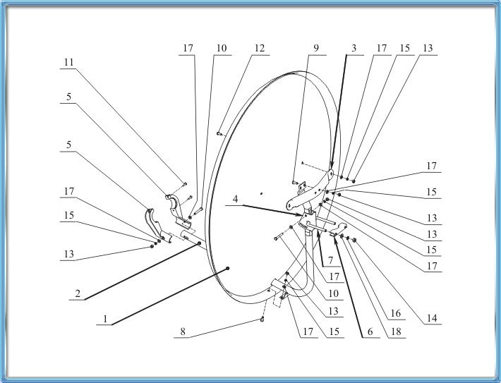
Below is a diagram of the assembly of the Kharkiv antenna with a diameter of 0.9m:
|
№п/п |
Name |
1 |
Dish |
2 |
Supporting boom |
3 |
Holder |
4 |
Swivel bracket |
5 |
Left/right holder |
6 |
Clamp |
7 |
Bracket |
8 |
Bolt M6x12 |
9 |
Bolt M6x16 |
10 |
Bolt M6x45 |
11 |
Screw M4x20 (self-tapping screw) |
12 |
Screw M6x14 (half-round) |
13 |
Nut M6 |
14 |
Nut M8 |
15 |
Washer ?6 grover |
16 |
Washer ?8 grover |
17 |
Washer ?6 |
18 |
Washer ?8 |
Assembly instructions

1. Bracket 7 is inserted into the swivel bracket 4. Clamp 6 is put on bracket 7 and 2 nuts M8 are screwed on through washers and grovers ?8. In the case of some satellites, the swivel bracket 4 needs to be turned over so that its adjustment slot is on top.
2. The supporting boom 2 is attached to the swivel bracket 4 using 2 bolts M6x45, washers ?6, grovers ?6 and nuts M6. During assembly, the bolt with the nut in the adjustment slot should not be tightened too much.
3. Holder 3 is attached to the supporting boom 2 using 2 bolts M6x16, washers ?6, grovers ?6, nuts M6.
4. The dish 1 is threaded through the hole at the bottom of the supporting boom 2. Dish 1 is connected to holder 3 using 2 half-round screws M6x14, washers ?6, grovers ?6 and nuts M6.
5. The dish 1 is connected to the supporting boom 2 at the bottom using 2 bolts M6x16, washers ?6, grovers ?6 and nuts M6.

6. If you are assembling an antenna for 3 satellites, you need to put on the supporting boom 2 multifeeds (additional holders for converters).
7. The holders 5 are inserted into the converter. The two halves of holder 5 are tightened with two screws 11. The assembled holder 5 is put on the end of the supporting boom 2 and is attached to it using bolt 10 M6x45, washers ?6, grover ?6 and nut M6.
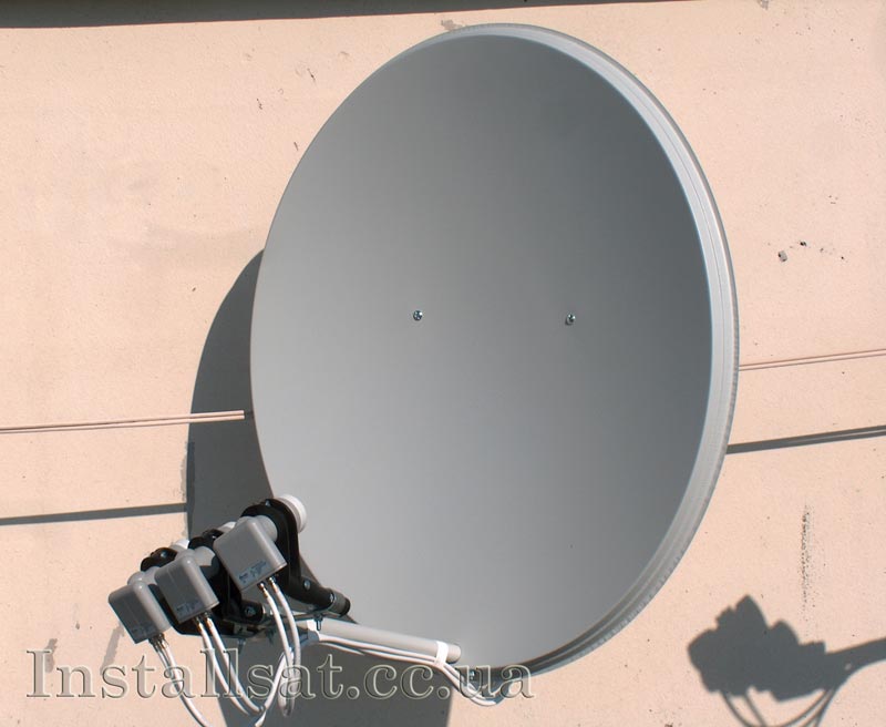
If there are installed antennas nearby, you can assemble your antennas according to their example.